Determining several microscope characteristics
Introduction
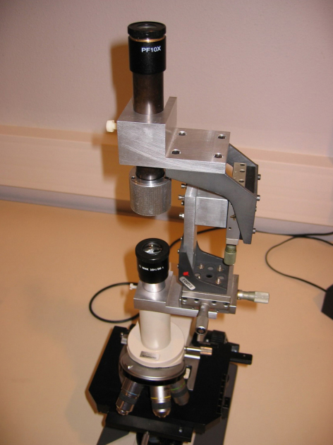
It is easy to determine or verify several optical characteristics of a given objective/eyepiece configuration. To do so, one has to first adjust the microscope (as detailed previously) on a particular preparation called “objective micrometer” which is made of a calibrated scale, usually to the 1/100th of millimeter, engraved on a transparent slide and covered with a standard coverslip of thickness \(0.17~mm\).
Measurement of the total optical power of a microscope
After aligning the microscope, the user places one eye behind the eyepiece and observes the micrometer scale highly magnified. By looking at this same image located at infinity through a telescope with a micrometric ocular previously angularly calibrated, it is possible to determine the angular size \(\Delta \theta\) of the image of \(N\) objective micrometer intervals (see Fig.17 and Fig.18). If the distance between two successive scales of objective micrometer is equal to \(\Delta x\), then we immediately deduce that the total optical power (dioptric power) of the microscope is:
\(\Delta \theta\), \(\Delta x\) and \(P_{micro}\) being respectively expressed in radian, meters and dioptres.
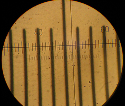
In figure 18, we can see that 4 intervals of the micrometer scale (at \(1/100~mm\)), i.e. \(0.040~mm\), are covering the telescope field of view between scale \(11\)(\(\pm \sim 1/2\)) and scale \(87\)(\(\pm \sim 1/2\)) (by taking in the two cases the left side of the micrometer line), i.e. therefore \(76 \pm \sim 1\) basic angular intervals of the telescope. Using a preliminary calibration of the telescope with a calibrated collimator, we could determine that an interval of the telescope micrometer corresponds to \(0.0482° \pm 1%\). Therefore, we deduce that \(\Delta \theta = 3.66° \pm \sim 2.3 \%\) and the total microscope power is:
By definition the microscope angular magnification factor is:
where \(d_{norm}\) represents the normalised value of the minimum distance for a in-focus visualization through a standard optically perfect eye; it is fixed to \(0.25~m\).
Using equations 2 et 3, we deduce that the microscope angular magnification factor is \(400 \pm 10\). This result is in perfect agreement with the value \(G_{c,~micro} = |g_{y,~obj}|\cdot G_{c,~oc}\) expected for an objective \(40×\) and an eyepiece \(×10\).
It is therefore possible to easily check (within the measurement uncertainty) the manufacturers labels engraved on the optics. One can note that when the eyepiece is micrometric, as it is the case here, the objective magnification \(|g_y |\) can be independently determined by directly comparing the scale of the micrometer objective image with the scale of the eyepiece micrometer (for which each interval corresponds to 1/10th of mm). One can also determine the ocular power \(P_{oc}\) by measuring with the auxiliary telescope the angle \(\Delta \theta_{oc}\) corresponding to \(N_{oc}\) intervals \(\Delta x_{oc}\) of the scales of the ocular micrometer, and using the equation \(P_{oc} = \Delta \theta_{oc} / ( N_{oc} \cdot \Delta x_{oc} )\). The corresponding measurements and verifications using figure 18 are left to the reader as an exercise.
Numerical aperture of the objective and microscope exit pupil (or eyepoint)
The relationship between the object-side numerical aperture \(NA_{obj}\) and the diameter of the eyepoint \(\diameter _{e,p.}\) can be seen on the aperture ray tracing for an object located on the optical axis, (see figure 2 in the course section). The schematic view below show the main features:
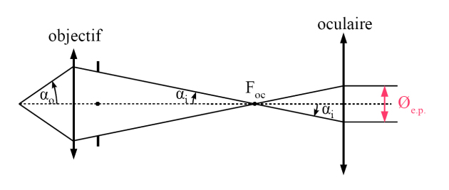
Since the objective and ocular are assumed to be aplanetic for their respective optical conjugations, it is possible to apply the Abbe sine condition (see the basic course on geometric optics). For the objective, this implies that the numerical apertures in the object and image spaces (the object and image medium being air, of refraction index 1), \(NA_{obj} = |sin \alpha_0 |\) and \(NA_{im} = |sin \alpha_i |\), are linked to the objective magnification, \(g_y\), by :
In addition, the Abbe sine condition for the conjugation focal point/infinity (see basic course of geometric optics or reference [ [1]]) of the eyepiece can be written (noting that the object-side numerical aperture of the eyepiece is identical to the image-side numerical aperture of the objective):
where \(f'_{ep}\) is the ocular focal distance.
By using the relation between the eyepiece angular magnification factor and its focal length ( \(G_{c,~oc} \overset{def}{=} d_{norm} / f'_{oc}\)), we obtain :
We note that the diameter of the microscope exit pupil is linearly proportional to the object-side numerical aperture of the objective and inversely proportional to the microscope angular magnification factor.
The eyepoint diameter can be measured using an additional calibrated viewfinder (see Fig.20 and Fig. 21a).
Attention :
To make a correct measurement of the eyepoint diameter using an additional viewfinder, one has to open the aperture diaphragm of the Köhler illumination condenser wide enough, otherwise it is the image of this diaphragm (which is formed in the same plane as the microscope exit pupil) that can be seen and measured with the viewfinder (see also figure 3 in the course section, where the various optical conjugations are indicated)
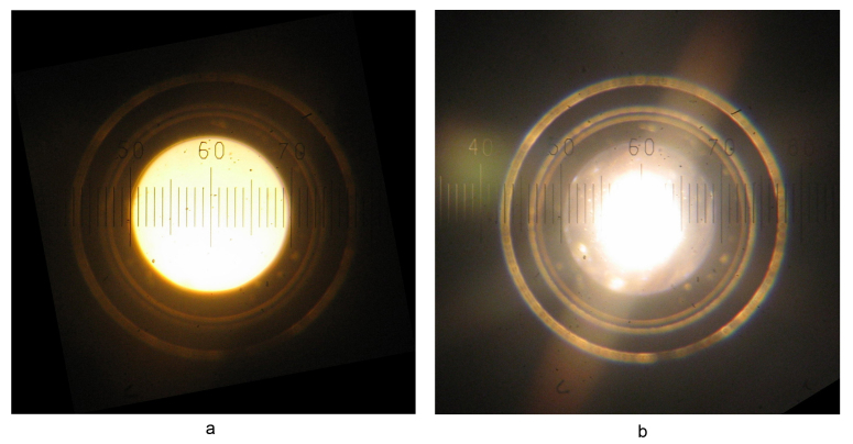
On figure 21a, it can be seen that the eyepoint diameter represents \(19,5\pm \sim 1\) intervals of the viewfinder scales. A preliminary calibration of the viewfinder using a micrometer showe that one interval on the viewfinder scale corresponds to \(42,9~\mu m \pm \sim 0.5 \%\). Consequently, the diameter of the microscope exit pupil is:
By using equation 6, one can obtain a value for the objective numerical aperture. As seen in the previous paragraph, the microscope angular magnification factor \(G_{c,~ep} \cdot |g_{y,~obj} |\) is equal to \(400(\pm 10)\) for the same objective/ocular pair, which allows us to obtain:
with \(d_{norm}=250~mm\).
This value is perfectly compatible with the indication \(0.65\) engraved in the mount of the \(40x\) objective used here.