Adjustments
The episcopic observation needs only small adjustments, because the Köhler illumination focus is preadjusted by the manufacturer to coincide with the objective focal plane. Therefore, the user only needs to turn on the illumination block, to adjust the micrometric ocular to its own sight, and to focus on the sample while being careful, as always, to avoid any collision between the objective and the sample (one should start with an sample several tens of millimeters below the objective frontal lens and then should move the sample away from the objective using the focus knobs). The user should then adjust the field diaphragm of the Köhler illumination system to illuminate only the observed region or the region of interest, if the latter is smaller, in order to limit the parasitic light. The last step is to optimize the focus on the studied objects.
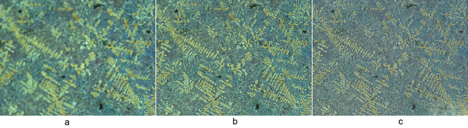
The user should also adjust the aperture diaphragm: indeed, if it open to its maximum the contrast is not optimum. For example, the contrast on photography 24 b) is much better that the contrast on photography a). In the case c), the aperture diaphragm is too closed.
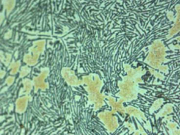
On photography 25, it can be noted that during the slow primary cooling phase, there was formation of large grains corresponding to a solid Al(Si) solution, and then, the temperature keeping decreasing, the eutectic point (\(577°C\)) was reached with formation of silicon needles.
This analyzing process is used to observe polished planes of materials whose phases show differences in reflexion. The applications mainly relate to the analysis of metal alloy or corroded structures, and to hardness measurements.
To measure Vickers hardness, an imprint is made with a indenter under a given load during \(15~s\). The applied force range between \(1\) and \(120~N\). The diamond indenter has a pyramidal shape with a square basis and with opposite faces making a \(136°\) angle.
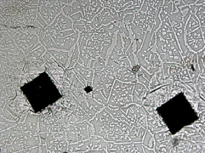
In the example presented on figure 26, a force of \(49~N\) is applied during \(15~s\). The measurement of the imprints diagonals allows calculating the Vickers hardness of the welding bead. The mean value of the diagonals measurements give \(185~\mu m\), which corresponds to a Vickers hardness of :
The force \(F\) is expressed in newton, and the imprint diagonal \(d\) in millimeters. In this particular case, the obtained value corresponds to a semi-hard material.
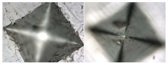
With an objective of magnification \(50\) and of numerical aperture \(0.80\), the sample surface and the imprint bottom cannot be simultaneously in focus (figure 27).
A microscope equipped with an objective \(\times 50\) and an eyepiece of angular magnification \(10\) has a angular magnifying factor of \(500\), which corresponds to a power of \(2000~\delta\), i.e. a focal distance of \(0.5~mm\):
Where \(d_{norm}\) represents the minimum normalized distance of distinct viewing for a normal eye; it is equal to \(25~cm\).
From the value of the microscope focal length, we deduce that the depth of field for a normal eye of dioptric amplitude \(a = 4 \delta\) is on the order of \(1~\mu m\):
A fine tuning of the microscope stage position allows measuring the order of magnitude of the imprint depth, which is of \(\sim 20~\mu m\). We note that this order of magnitude is in very good agreement with the calculated value, since the penetration depth is linked to the diagonal measurement by the relation: