Exercises
A microscope is made of an objective that we assume to be a thin lens of focal length \(f'=5.25~mm\) and a Huygens eyepiece (3,2,1) of focal length \(f'_{oc} = 16.5~mm\).
The characteristics of such an eyepiece are summarized on figure 28.
\(\phi _1\) and \(\phi ' _1\) are the object and image focal points of the field lens \(L_1\), of focal length \(f'_1\).
\(\phi _2\) and \(\phi '_2\) are the object and image focal points of the eye lens \(L_2\), of focal length \(f'_2\).
\(F_2\) and \(F'_2\) are the object and image focal points of the eyepiece.
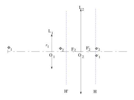
We note that the 'symbol' \((m,p,q)\) characterizes an ocular with two thin lenses by \(\dfrac{f'_1}{m} = \dfrac{e}{p} = \dfrac{f'_2}{q} = \textit{£}\) where e is the interstice of the doublet \(\overline{O_1 O_2}\). For a Huygens ocular \((3,2,1)\), we have the particular properties: \(f'_{oc} = \dfrac{3}{2} \textit{£}\), \(\overline{O_1 O_2} = 2 \textit{£} = \dfrac{4}{3} f'_{oc}\), \(\overline{O_1 F_2} = \dfrac{3}{2} \textit{£} = f'_{oc}\) and \(\overline{O_2 F'_2} =\dfrac{\textit{£}}{2} = \dfrac{1}{3} f'_{oc}\),
with, in this case \(\textit{£} = \dfrac{2}{3} \times 16.5~mm = 11.0~mm\).
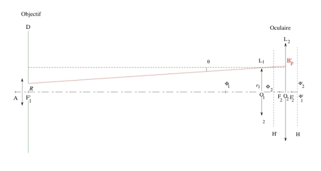
The schematic view of the whole microscope is represented on figure 29.
The radius of the eyepiece lens \(L_1\) is \(r_1 = 6~mm\), and the radius \(r_2\) of lens \(L_2\) is large enough so that no ray passing through \(L_1\) is stopped by \(L_2\). The image of an object point \(A\) by the objective is a point \(A'\) that coincides with the object focal point \(F_2\) of the eyepiece. In the air, the objective is aplanetic for the couple of points \((A, A')\) located on the optical axis. The numerical aperture is limited by the circular diaphragm \(D\) located at the image focal plane of the objective, and is equal to \(0.65\).
The microscope optical interval, i.e. the distance between the objective image focal point \(F'_1\) and the eyepiece object focal point \(F_2\), is \(\Delta =210~mm\). This value is used in some metallographic microscopes of tube length \(230~mm\).
Question
Why are we using the configuration where the objective image is located at the eyepiece object focal point \(F_2\)?
Solution
In order to not tire the eye, the observer adjusts the eyepiece position so that the image given by the whole microscope is at infinity. The intermediate image given by the objective is therefore located at the front focal plane of the eyepiece.
Question
What does the sentence « the objective is aplanetic for the couple of points \((A, A') \ll ~mean\)?
Solution
This means that the two frontal planes passing through points \(A\) and \(A'\) are conjugated, i.e. that the Abbe sine condition is verified for this pair of planes.
Question
Calculate the objective magnification.
Solution
The system studied here is the objective, with a pair of conjugate planes passing through points \(A\) and \(A'\) chosen as origins; the transverse magnification of this system corresponds to the nominal magnification of the objective \(g_{y,~obj}\):
i.e. :
The "minus" sign means that the image located at \(A'\) is inverted.
Question
What is the value of the intrinsic optical power of the full microscope?
Solution
Applying the relations defining the power and intrinsic power, the microscope optical power can be expressed in the following way:
where \(f'_{micro}\) represents the image focal distance of the microscope, that is to say of the ensemble eyepiece-objective; \(\theta ''\) is the angle through which the final image is seen, and \(AB\) represents the object size. Introducing the intermediate image size \(A'B'\), we obtain:
\(P_{i,~oc}\) represents the ocular intrinsic power. The microscope intrinsic power \(P_{i,~micro}\) is equal to the product of the objective magnification and the ocular intrinsic power.
Expressing the ocular intrinsic power as a function of its focal length \(f'_2\), we obtain:
Question
Calculate the microscope angular magnifying factor; express it as a function of the absolute value of the objective transverse magnification \(g_{y,~obj}\) and the eyepiece angular magnification \(G_{c,~oc}\)
Solution
The angular magnifying factor is given by:
or
The microscope angular magnifying factor \(G_{c,~micro}\) is equal to the product of the objective transverse magnification and the ocular angular magnifying factor. Those two values are indicated on the objective and ocular mounts.
Question
Determine the radius \(R\) of the aperture diaphragm \(D\); deduce the position and radius \(R'\) of the exit pupil. What is the value of the eye relief ? Is it large enough to allow for an observation with eyeglasses?
Solution
By applying the Abbe sine condition to the couple of points \(A\) and \(A'\):
we obtain:
since, here, \(n = n' = 1\).
On figure 30, we note that:
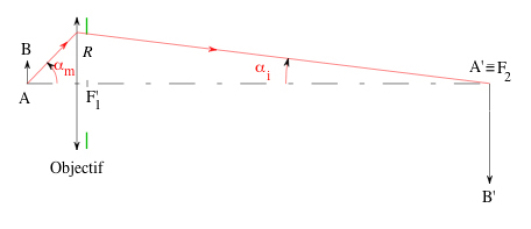
For a microscope, the value of the angle \(\alpha_m\) is large, since the numerical aperture of an objective is generally as large as possible in order to see the object details with a great resolution. By contrast, the angle \(\alpha_i\) is small (in absolute value) according to formula 1, because of the division by the absolute value of the objective magnification (\(40\), in this case); consequently, we can make the approximation \(tan \alpha_i \simeq sin \alpha_i\), from which we deduce :
i.e.:
The eyepoint (i.e. the microscope exit pupil) is the image \(D'\) of diaphragm \(D\) given by the eyepiece. We can apply Newton's equation to the pair of points \((D,D')\):
We therefore obtain, noting that \(\overline{DF_2} = \Delta\) :
The eyepoint and the image focal plane of the eyepiece are always very close to each another.
Since the eye pupil must be placed on the eyepoint for an optimal observation without vignetting, it is interesting to determine the eye relief, that is to say the distance between the eyepoint and the ocular eye lens. By using a property of a Huygens ocular \((3,2,1)\) : \(\overline{O_2 F'_2} = f'_{oc}/3\) we deduce the value of the eye relief:
This value is very small, not large enough to allow an observation with eyeglasses. This is one of the drawbacks of Huygens oculars, which are replaced on current high-quality microscopes with more complex combinations of 4 to 5 lenses, with an eye relief far larger.
The exit pupil radius can be inferred by the magnification formula applied to the pair of points \(D, D'\):
from which we deduce a radius of \(0.27~mm\) for the eyepoint. One can note that the microscope exit pupil is smaller than the eye pupil (diameter \(\sim 2~mm\) for an observation by bright daylight); consequently the eye doesn't introduce any additional limitation, and the system aperture is really determined by the objective numerical aperture.
Question
Determine the “full-light” field in the object space (i.e. the field for which the whole cone of light rays entering the pupil gets through the microscope without being stopped), the corresponding angular field in the image space, the location and radius of the diaphragm that could be inserted to suppress the vignetting effect at the periphery of the total field.
Solution
The microscope intermediate space containing the diaphragm \(D\), the intermediate image \(A'B'\) and the eyepiece field lens \(L_1\) is represented in figure 31. An object \(A\) located on the optical axis gets imaged in \(A'\). If the object moves away from the optical axis, its images moves towards \(B'_t\). A ray that would make a higher angle with the optical axis than the blue ray (on the figure) would be stopped by the eyepiece field lens. The lens \(L_1\) is therefore the field diaphragm since by hypothesis no ray going through \(L_1\) can be stopped by \(L_2\). Since the aperture diaphragm and the only field diaphragm are located between the objective and the eyepiece field lens, it's easy and natural to choose this intermediate space to determine the “full-light” field .
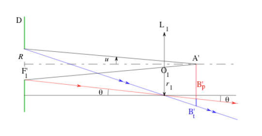
On figure 31, the rays traced in red and blue correspond, respectively, to the limit of the “full-light” field and the total field. We can apply the trigonometric relations:
Recalling that \(\overline{F'_1 F_2} \overset{def} \overline{F'_1 A'} \overset{def} \Delta\) and using the Huygens ocular properties \(\overline{O_1 A'} = \overline{O_1 F_2} = f'_{oc}\) (figure 29), we obtain:
In the object space:
The diameter of the object-side “full-light” field is therefore equal to the double of this value, i.e. roughly \(0.31~mm\). To determine the “full-light” field in the microscope image space, we can calculate the half-angle field for the ocular, corresponding to \(A'B'_p\):
We can deduce that the “full-light” field in the image space, \(\theta '\), is roughly equal to \(41.2°\).
To suppress the contour field (i.e. the darkening region at the periphery of the full field), a diaphragm must be inserted at a real image location; it is not possible to insert it at the image given by the objective since this is a virtual image located behind the ocular field lens. Therefore, the diaphragm is inserted at the image \(A'\) given by the field lens. The thin lens conjugation equation applied to the field lens \(L_1\) gives:
where \(A”\) is the image of \(A'\) given by \(L_1\); using the properties of a Huygens ocular that were mentioned in the introduction to the exercises, and by noting that \(A'\) is superimposed with \(F_2\), we calculate a distance of \(+11~mm\) for \(\overline{O_1 A''}\).
The transverse magnification associated with the couple of planes going through \(A'\) and \(A"\) is equal to:
The diaphragm must therefore have a radius r corresponding to the “full-light” field calculated in the intermediate space located between the field lens and the eye lens of the ocular:
Question
Evaluate the focusing range.
Solution
The focusing range represents the distance from which the object can be axially displaced without significantly damaging the image. It depends on the observer dioptric amplitude (i.e. its own focusing range), and of the focal distance of the considered system:
for a user “accomodation” power (focusing range) of \(4\delta \).
This focusing range decreases when the microscope optical power increases.