
Animations
 |
Animations |
 |

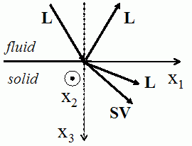 The interaction of
an oblique plane wave with an interface separating a fluid medium from
an isotropic medium causes a reflected
wave in the fluid medium and two transmitted
waves in the solid medium:
a longitudinal wave L (the particles vibrate in the
propagation
direction of the wave) and a shear vertical wave SV (the
particles
vibrate in the direction perpendicular to the propagation direction of
the wave).
|
The
whole field in the fluid medium, which is the summation of the incident
and reflected fields, has always a stationary
character in the direction perpendicular to the interface
(following x3), and a propagative
character in the direction of the interface dans la direction de
l'interface (following x1).
 < < cL< cL< cT cT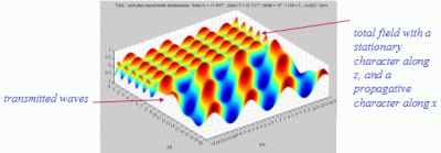 The whole field in the solid medium is the summation of the longitudinal and of the shear fields, each one propagating following its respective propagation direction. |
| Generally
speaking, the propagation velocity cf
of the waves in a fluid medium is inferior to that of the waves in a
solid medium, and thus cf<cT<cL
where cL and cT are the
velocities of the longitudinal and shear waves respectively. In this case,
there exist two values for the incident angle, denoted respectively
 cL and cL and  cT and called
respectively 1st
and 2nd critical angles for the given interface, such
that sin cT and called
respectively 1st
and 2nd critical angles for the given interface, such
that sin  cL
= cf/cL and sin cL
= cf/cL and sin  cT = cf/cT . cT = cf/cT .- When
 < < cL< cL< cT , the two
transmitted waves are both propagative. cT , the two
transmitted waves are both propagative.- When
 cL< cL< < < cT , the
longitudinal transmitted wave is evanescent and the shear transmitted
wave is propagative. cT , the
longitudinal transmitted wave is evanescent and the shear transmitted
wave is propagative.- When
 > > cT > cT > cL,
the two transmitted waves are both evanescent. The modulus ot the
reflection coefficient in the fluid medium thus becomes equal to 1 Le
coefficient de
réflexion dans le milieu fluide devient alors
égal
à 1 (total
reflection), but acoustic energy is always present in the
solid medium. cL,
the two transmitted waves are both evanescent. The modulus ot the
reflection coefficient in the fluid medium thus becomes equal to 1 Le
coefficient de
réflexion dans le milieu fluide devient alors
égal
à 1 (total
reflection), but acoustic energy is always present in the
solid medium.An evanescent
transmitted wave propagates in a direction parallel to
the interface, while its amplitude has an exponential decreasing with
the depth (when x3 increases), in a direction
perpendicular to the
interface.
|
 cL< cL< < < cT cT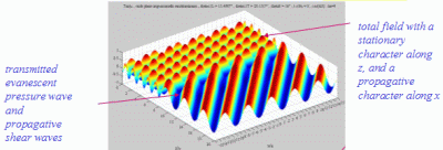  > > cT > cT > cL cL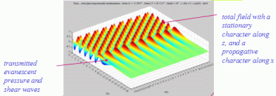 |
| The
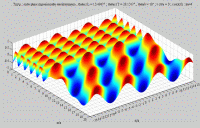
cartographies below represent the amplitude of the real part of the
projection on the x3-axis of the stress vector (T33)
which corresponds, in the fluid medium, corresponds to the opposite of
the acoustic pressure; color level (red = maximum, blue = minimum). The oblique black lines represent incident, reflected and transmitted rays, as they are predicted by Snell-Descartes' laws: when the transmitted waves are propagative (  < < cL< cL< cT),
each one propagates in the direction of its transmitted ray, this
direction being perpendicular to the wave planes. cT),
each one propagates in the direction of its transmitted ray, this
direction being perpendicular to the wave planes. |
|
Incident angle inferior to both
critical angles
 < < cL< cL< cT . cT . |
|
|
Longitudinal transmitted wave,
alone,
 < < cL< cL< cT cT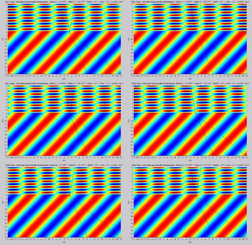 |
Shear transmitted wave, alone,
 < < cL< cL< cT cT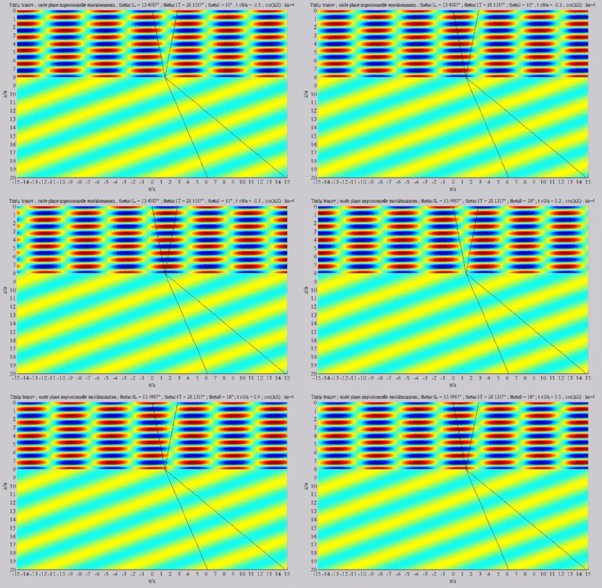 |
|
Summation of the longitudinal and
of the shear fields (transmission)
 < < cL< cL< cT cT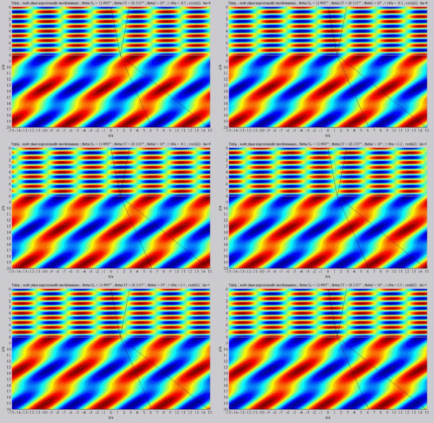 |
|
Incident angle included between
the two critical angles  cL< cL< < < cT . cT . |
|
Longitudinal transmitted wave,
alone,  cL< cL< < < cT . cT .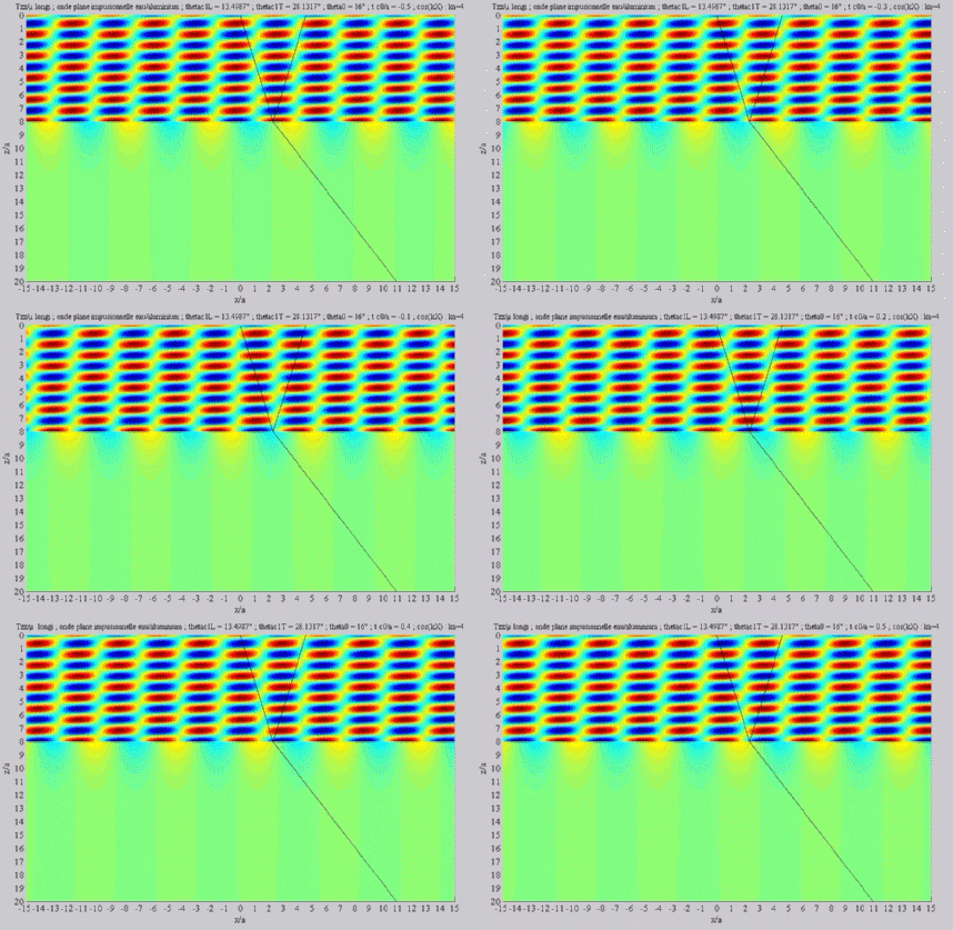 |
Shear transmitted wave, alone,  cL< cL< < < cT . cT .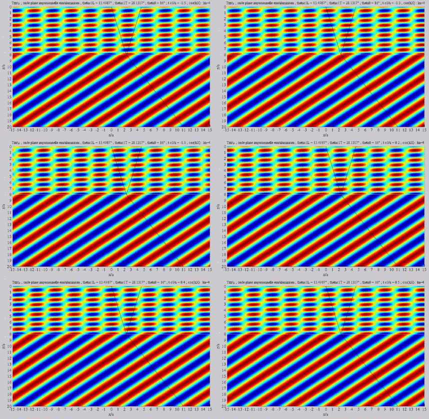 |
Summation of the longitudinal and
of the shear fields (transmission)  cL< cL< < < cT . cT .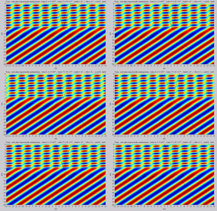 |
|
Incident angle superior to both
critical angles
 cL< cL< cT < cT < . . |
|
Summation of the longitudinal and
of the shear fields (transmission)  cL< cL< cT < cT < . .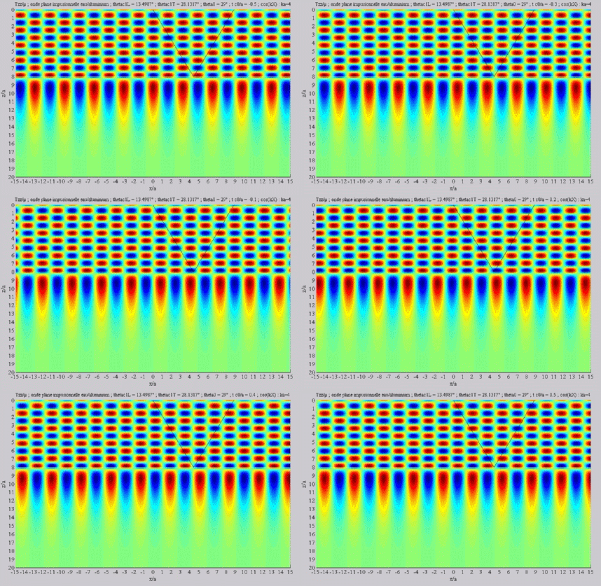 |
|