Exercise : pulsed laser lighting
To define an interferometric sensor, we need the photometric balance of the object illumination system and the image capture.
The object of interest is in albedo steel \(\rho_{d} =7\%\) and with a diameter of \(\phi_{0} =300\text{ mm}\). The imagery objective has a focal length of \(f'=18\text{ mm}\), a transmission of \(T_{opt}=90\%\) and has an aperture ring with the following apertures: \(N_{0}=\{ 2.8 ;4 ;5.6 ;8 ;11.3 ;16 ;22.6 ;32\}\). For layout reasons, the object will be illuminated with a medium incidence of \(\theta =30°\).
The CCD sensor used has a size of \(M\times N=1024\times 1360\text{ pixels}\) (of a size of \(p_{x}=p_{y}=4.65\text{ mm}\)). Each pixel contains \(N_{sat}=18,000\) electrons at the saturation point and the pixel frequency is of \(20\text{ MHz}\). The integration time can be adjusted between \(5\text{ ms}\) and \(65\text{ s}\).
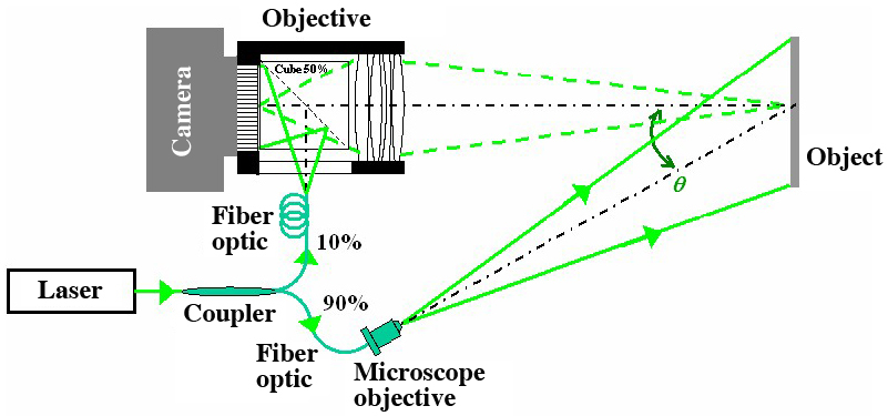
We use an NdYAG pulsed laser doubled with a KDP crystal. The laser pulses delivered have a duration of 20 ns. The laser can have a rhythm between \(30\) and \(60\text{ Hz}\). The experimental device of laser imagery is described in Figure 2. A variable transmission coupler (not described here) separates the laser wave in an "object illumination" (transmission \(\tau\)) and a "reference" part that illuminates directly the sensor (transmission \(1-\tau\)) through the cube (\(T_{c}=50\%\)). For the first rough estimate, we will suppose that there's no loss in the coupler.
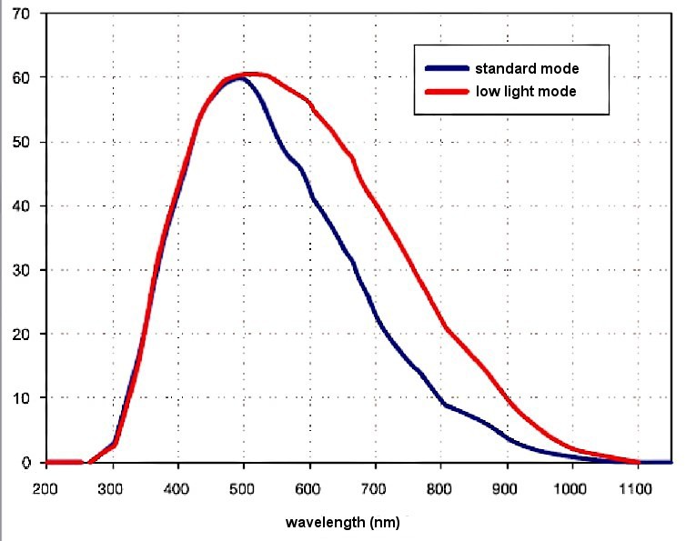
In Figure 3, we can see the sensor's quantum efficiency curve, when used in standard mode.
In this exercise, the aim is to assess the power PL and energy QL needed by the laser. To decide on the orders of magnitude, we will focus on the sum of the light energies of the object and reference beams.
Fondamental constants:
Planck's constant: \(h=6.6256\times 10^{-34}\text{ J.s}\)
Speed of light: \(c=299792458\text{ m.s}^{-1}\)
Boltzmann's constant: \(k=1.380662\times 10^{-23}\text{ J.K}^{-1}\)
Electron charge: \(q=1.60217653\times 10^{-19}\text{ coulomb}\)
\(1eV\approx 1.60217653\times 10^{-19}\text{ J}\)
Question
The image of the zone we are interested in must cover the entire sensor. What must the lateral magnification g between the object plane and the recording plane be? Deduce the draining zone position compared to the camera.
Solution
The object-image lateral magnification must equal:
where the sign of \(\gamma\) is negative. The digital application gives:
We note that \(\gamma =-0.0158\). The lens is assimilated with a thin lens with a center \(O\), such that the position of object (\(A\)) is given by:
That is:
Hence, the object is located at a distance of \(1.157\text{ m}\) from the camera.
Question
Deduce from the previous question the spatial resolution inside the object plane.
Solution
Spatial resolution \(\rho_{x}\) is due to the size of the pixel which is projected on the object.
That is:
Question
Give the relation between \(P_{L}\), \(Q_{L}\) and \(\delta t\). What is the illumination produced by the laser in the object plane?
Solution
We have:
The laser power transmitted by the variable coupler is \(\tau P_{L}\). The illumination produced by the laser in the plane of the object is simply:
Question
Question
Calculate the illumination produced by the object in the image sensor plane.
Solution
Taking into account the cube transmission and the imaging optics, illumination is calculated as follows:
Question
Calculate the number of photoelectrons obtained for 1 pixel, \(N_{e^{-}}\), for the duration of the laser impulse, according to \(E_{R},p_{x},p_{y}\), \(\delta t\), \(\lambda\), \(h, c\), \(\eta\); then express \(N_{e^{-}}\) according to \(Q_{L},p_{x},p_{y}\), \(\delta t\), \(\lambda\), \(h, c\), \(\rho_{d}\), Topt , \(\tau\), \(T_{c}\), \(\theta\), \(N\) et \(\gamma\).
What is the value of the image sensor's quantum efficiency (\(\eta\)) ?
Solution
According to the results of the Case Study, for a pixel with a surface \(p_{x}\times p_{y}\) the number of photo-electrons generated by the incident illumination during a length of time equal to the laser pulse \(\delta t\) and for a wavelength \(\lambda\), is:
With the parameters of the previous solution, the following result is obtained:
According to the curve of figure 3, for \(\lambda =532\text{ nm}\) we have \(\eta\simeq 0.5\).
Question
What is the number of photoelectrons generated by the reference beam? We'll suppose that all the laser energy illuminates the sensor's surface.
Solution
The solution can be found using the previous reasoning. The illumination produced on the sensor by the reference beam is:
The number of photo-electrons is thus :
Question
Express the value of the laser energy \(Q_{L}\) in order to saturate at least a quarter of each pixel, for each beam (reference beam and object beam). Calculate \(Q_{L}\) for \(N_{o}=2.8\), \(N_{o}=8\) and \(N_{o}=32\). Display the results in a table and give your comments on them.
Solution
In order for \(N_{e-}\geq N_{sat}/4\) to be true, we obtain the minimum laser energy for the object-beam:
and for the reference beam:
The calculation uses the data from table 5. The transmission of the variable coupler is chosen at \(\tau =0.999990\). This way, only \(10\) to \(13\%\) of the laser energy is sent to the reference beam.
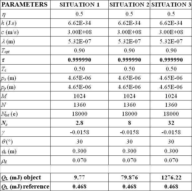
We can observe that the energy required to produce \(N_{e-}\geq N_{sat}/4\) photo-electrons is markedly higher on the object path than that calculated on the reference path. This result is logical. Indeed, the reference beam impacts the sensor directly, whereas the object beam is scattered/diffused by the object toward the sensor. This means that if we were to actually obtain \(N_{e-}\geq N_{sat}/4\) for both beams, then the reference path would have to be even more reduced, by a value in the order of \(5\times 10^{-5}\%\).
Also note that when working with a less open lens, the required laser energy is considerable: more than \(1\text{ kJ}\) in situation 3.
If situation 1 is considered acceptable and the laser is rated at \(50\text{ Hz}\) then the average power of the laser will be in the order of \(488\text{ mW}\) of the object of \(300\text{ mm}\) of diameter. This generates a significant cost to the laser source. If the object is smaller, the laser power will be weaker and the cost lower. The required laser energy may be lowered by increasing pixel size. However, this will be at the detriment of spatial resolution on the object.
Question
What is the best strategy to adopt in order to acquire images if one wish to study the object while it is vibrating between \(5\text{ kHz}\) and \(10\text{ kHz}\)?
Solution
An estimate of the maximum acquisition rate of the image sensor can be carried out. The CDD sensor comprises \(M\times N=1024\times 1360\text{ pixels}\) and the pixel frequency is \(20\text{ MHz}\). Therefore, we obtain:
The laser rate (\(30\text{ Hz à } 60\text{ Hz}\)) and the sensor rate do not allow us to study the vibration in real time. Hence, we can only study stationary objects, i.e. objects excited with a frequency that is constant in time. Therefore, we must synchronize with the object and record the images stroboscopically. We realize the following: since the minimum sensor exposure time is \(5\text{ }\mu\text{s}\), the sensor must be triggered with a laser pulse chosen within the firing sequence. The laser pulse itself will occur slightly later than the vibration excitation signal of the object. By recording a sequence of laser pulses out of phase with the vibration and covering a vibration period, we can infer the amplitude and the phase of the mechanical vibration.