ULTRASONIC NON DESTRUCTIVE EVALUATION AND NON DESTRUCTIVE TESTING OF ANISOTROPIC COMPOSITE MATERIALS
 Version
française
Version
française 

|
|
ULTRASONIC NON DESTRUCTIVE EVALUATION AND NON DESTRUCTIVE TESTING OF ANISOTROPIC COMPOSITE MATERIALS Version
française |
|
| Work performed at or in
collaboration with
Laboratory Roberval of Université de Technologie de
Compiègne |
 |
 |

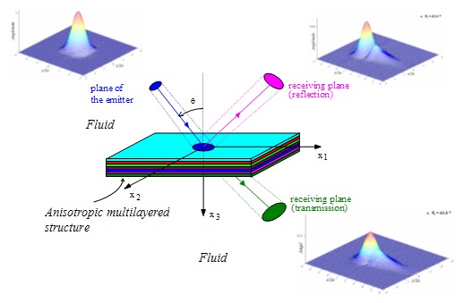 |
In
order to model in a correct manner the bounded
nature of
transducers,
the propagation model
with plane waves in
anisotropic multilayered
media has been extended to bounded
beams. The used method relies on the decomposition of the
beam in monochromatic plane waves, using the angular spectrum
method [A7, A13, O'2, B4, B5, C4].
It allows to obtain the reflected and transmitted beams through an
immersed composite plate, for a 3D geometry.
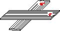
At
a
characteristic pair (angle
 of the acoustic axis,
frequency), the acoustic beam generates locally a modal wave (Lamb or
Rayleigh wave for instance) while the bounded
nature of the beam rather provokes a modal wave
beam in the structure. This
modal beam re-radiates in the fluid. In the case of an anisotropic structure,
the
direction of the modal wave beam is deviated with respect to the
sagittal
plane, determined by the incident bounded beam.
In the case of a unidirectionnal composite plate, following the chosen
Lamb mode, the modal beam may be deviated in the direction of the
fibers.
More... of the acoustic axis,
frequency), the acoustic beam generates locally a modal wave (Lamb or
Rayleigh wave for instance) while the bounded
nature of the beam rather provokes a modal wave
beam in the structure. This
modal beam re-radiates in the fluid. In the case of an anisotropic structure,
the
direction of the modal wave beam is deviated with respect to the
sagittal
plane, determined by the incident bounded beam.
In the case of a unidirectionnal composite plate, following the chosen
Lamb mode, the modal beam may be deviated in the direction of the
fibers.
More... |
|
|
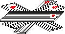
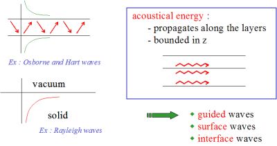 Fig. 1 Fig. 1 |
A modal
wave [see W.D.
Hayes, "Conservation of action and modal wave action", Proc. Roy.
Soc. Lond. A., 320,
187-208, (1970)] is a wave for which the acoustical energy
propagates along the layers, whereas it remains bounded in a direction (z) perpendicular to the
layer (guided waves, surface waves, interface waves).
Modal waves need one or more boundaries to construct themselves: the acoustic energy propagates in the directions of some subspace of the physical space, whereas these waves present a stationary character in the supplementary subspace (in the sense of the linear space theory). |
 of the form
 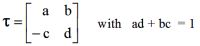 .
.
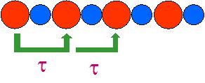 Periodic diatomic chain of atoms
|
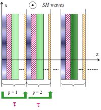 SH waves in isotropic layers |
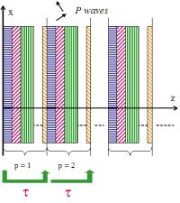 Longitudinal waves in fluid layers |
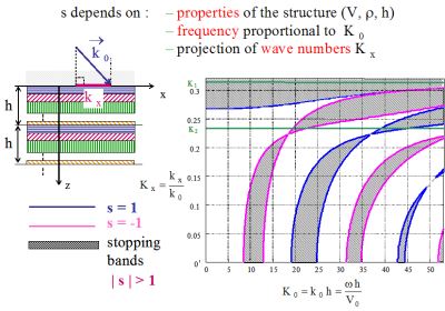 Fig. 2 Fig. 2 |
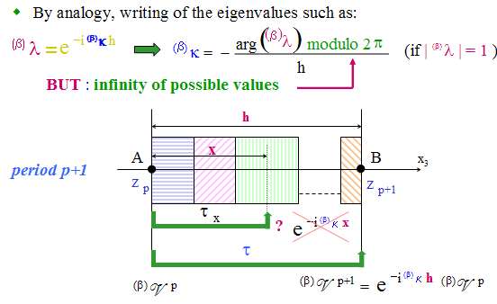
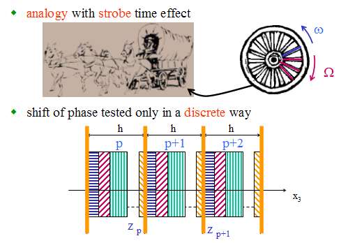
The Floquet
waves which propagate in the periodic structure are linked to
the eigenvalues
 (and
to the eigenvectors) of the transfer matrix , which are solutions
of the characteristic equation (and
to the eigenvectors) of the transfer matrix , which are solutions
of the characteristic equation 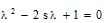 with s=(a+d)/2.
When
is complex (modulus equal to unity), the associated Floquet wave is
propagative, whereas it is evanescent when
is real. with s=(a+d)/2.
When
is complex (modulus equal to unity), the associated Floquet wave is
propagative, whereas it is evanescent when
is real. When the Floquet waves are evanescent, the corresponding domain in the frequency/angle plane (K0,Kx) is called stopping band (or stop band). When the Floquet waves are propagative, the corresponding domain is called passing band (or pass band). These names correspond to the fact that, for a semi-infinite periodic structure, the acoustic energy is totally reflected in the external medium for stopping bands, whereas, for passing bands, a part of the energy goes into the semi-infinite periodic structure and radiates to the infinity. The stopping and passing bands of the structure correspond respectively to the case |s|>1 and |s|<1. These zones are separated in the plane (K0,Kx) by curves s(K0,Kx)=+1 or s(K0,Kx)=-1 (see Fig. 2 in the case of 2 layers in a period). |
 Fig. 3 Fig. 3 |
Guided
modes
Periodically multilayered medium made up of P periods (see Fig. 3). The transfer matrix P of the whole medium
can be calculated in
terms of ,
by means of Tchebychev polynomials of the second kind Up(s),
using Cayleigh-Hamilton theorem: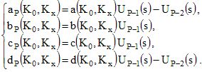 If the
periodic finite structure is surrounded by vacuum, the boundary
conditions at
the external interfaces imply that the stresses vanishes (TP=0 and T0=0), which
leads to a factorized
eigenmode equation: cP(K0,Kx)=0 i.e. c(K0,Kx)
UP-1(s)=0 , which leads to two
families of modal waves.
|
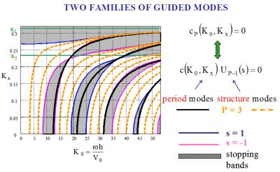 Fig. 4 Fig. 4 |
- The
first family of modal waves corresponds to what may be termed structure
modal waves. It is given by the condition UP-1(s)=0. From
the properties of Tchebychev polynomials, the (P-1) roots of this condition
are such that |s|<1,
which amounts to saying that these modes do occur in passing
bands.
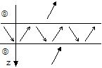
For the periodically fluid medium of Fig. 4 with P=3 periods, it can be
seen that there are 2 structure modes in each passing band (dashed
orange line).
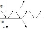
- The second family of modal waves corresponds to
what may be termed period
modal waves. It is given by the condition c(K0,Kx)=0, which
is independent of the number P of periods and thus corresponds
to modal waves which are directly linked to the period cell and which are such as |s|>=1. As a
consequence, the period modes are located in
the stopping
bands or on their boundaries (see Fig. 4, solid black
line).
|
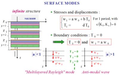 Fig. 5 Fig. 5 |
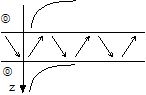
Surface
modal waves in a semi-infinite structure in contact with vacuum - Such a surface modal wave may
exist in a semi-infinite fluid periodic structure in contact
with
vacuum, whereas it does not exist in a single fluid medium.
- Under conditon c(K0,Kx)=0, when the first interface of the structure is
in contact
with vacuum, the condition T0=0
implies the condition T1=0
and so
on for other
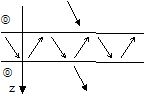
period interfaces. In particular,
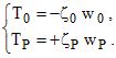
afterp periods, the normal
displacement is such as wp=ap
w0.
- Since the structure is semi-infinite, the integer p grows indefinitely as z tends to infinity. Thus, if |a|<1 then the amplitude of the wave, observed at each period interface, will decrease as a function of z, whereas if |a|>1 it will increase (see Fig. 5). |
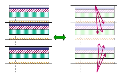
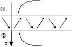
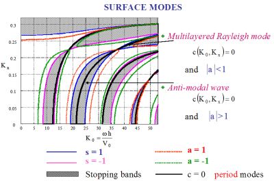 Fig. 6 Fig. 6 |
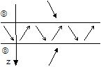
- The first case corresponds to a surface modal waves (which has been called a "multilayered Rayleigh mode"). - The second one
corresponds to what may be called an "anti-modal
wave": such
a modal solution has poor physical meaning since its amplitude is not
bounded
at infinity.
- It should be noted the crucial role that plays here the periodic character of the structure: actually, in the case of semi-infinite homogeneous fluid media, there is no surface modal wave, similar to that which has just been described for a periodically structure. - When the layers are stacked in inverse order, the surface modal wave and the "anti-modal wave" are exchanged. |
|
Boundary conditions
 |
Eigenmode equation
(dispersion equation) : |
|
 0 +P = 0 : factorized
eigenmode equation 0 +P = 0 : factorized
eigenmode equation |
0 =P : non factorized
eigenmode equation |
|
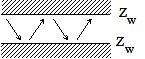
| Rigid wall: Zw
tends to infinity or vacuum: Zw = 0 |
 |
|
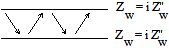
| Pure reactive impedance | 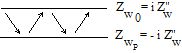 |
 |
| Propagative waves in the same external fluid medium |
 Total transmission |
 Generalized modal waves (kx is not real) |
 Total transmission |
 Anti-generalized modal waves (kx is not real) |
|
| Evanescent waves in the same external fluid medium |
 Anti-modal waves |
 Anti-modal waves |
 Anti-modal waves |
 Osborne and Hart modal waves |
|
|
A pultruded glass fiber reinforced plastic composite beam has been impacted. The considered profile stacking sequence is an alternating of 5 continuous mat and roving layers, with mat on the outer surfaces (contact : Thierry Chotard) |
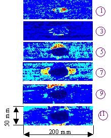 |
A C-scan ultrasonic cartography at different positions relative to the impact point permits classical results to be observed : below the impact point (on the rear surface), the zone of damage is larger than that on the surface of impact. |
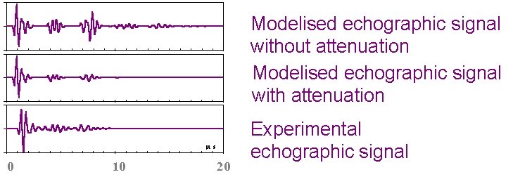 |
By taking into account the real response of the transducer, the echographic response of the medium [A6, B4], thanks to the model. |


 Symmetric mode S0

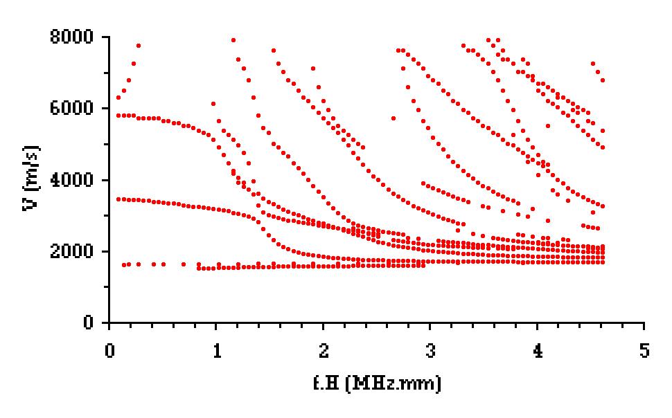

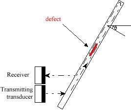
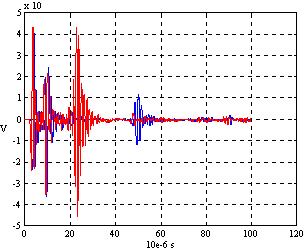

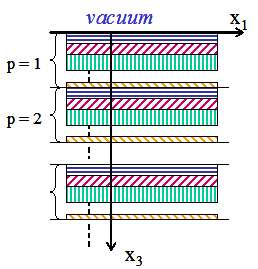
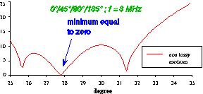
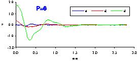

 Fig. 1
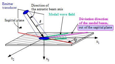 Fig. 2
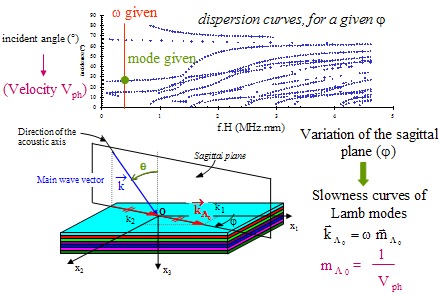

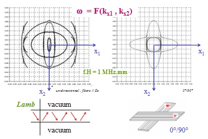 Fig. 4
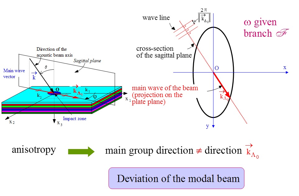
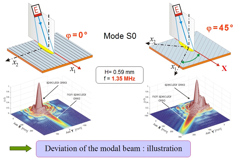
 Fig. 7
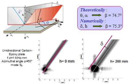 Fig. 8

 Fig. 9
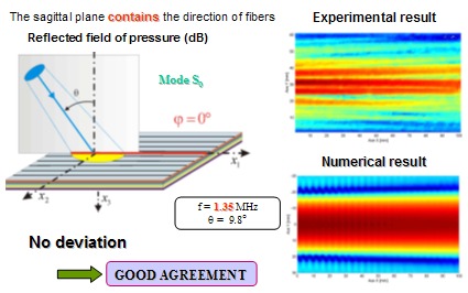 Fig. 10
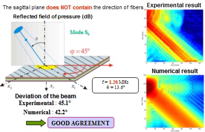 Fig. 11