Time delay and integration
Remarque :
The Time-Delay and Integration, TDI, is similar to register multiple exposures of a same moving object and adds them.
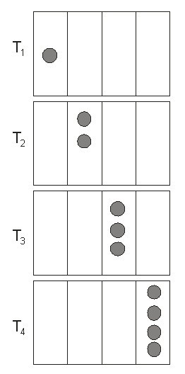
This addition automatically takes place in the charge well and it is the temporal synchronization of the sensor that produces multiple images. As the typical application of the TDI, we consider a simple camera lens which reverses the image of the object so that it moves at the opposite of the object movement. As the image is scanned along the matrix, charge packets are synchronized at the same speed. For a flatbed scanner, the document is fixed and the camera or a mirror moves. The figure 13 illustrates the working of four detectors in TDI mode. At the time \(T_{1}\) the image is on the first detector and creates a charge packet. At \(T_{2}\), the image is transferred to the second detector. Simultaneously, the clock pixel transfers the charge packet to the well of the second detector. Here, the image creates an additional charge which is added to the charge created by the first detector. The signal (charge) increases linearly with the number of detectors in TDI. The noise also increases but like the square root of the number of elements in TDI, NTDI. This results in an increase of the signal-to-noise ratio in \(N_{TDI}^{1/2}\). It is the well capacity that limits the maximum number of TDI elements that can be used.
Remarque :
For this concept of TDI to be working, the charge packet has to always be synchronized with the moving image. The precision with which the speed of the image is known drastically limits the use of TDI systems.